Chiltrix CX34 v1 - A few years with the Chiltrix...
What's a Chiltrix???
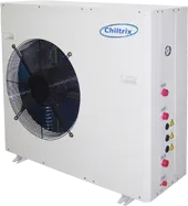
The Chiltrix CX34 is an air-to-water heat pump (also known as a hydronic heat pump or reverse-cycle chiller). A few years ago, I decided to replace the oversized and broken heat pump system that was previously installed in my house. After investigating a few other options (all heat-pumps of some sort, all with backup heat strips) I decided to do the non-standard thing (surprise) and go with this unit.
Reasoning
The main reasons I went with the Chiltrix CX34 over a "conventional" heat-pump are:
- Low power consumption - the CX34 uses less than 15 amps during 100% use. This is great for my (possible) future plans to become grid-independent yet completely comfortable.
- Efficient - The CX34 uses an inverter powered variable-speed compressor as well as fully adjustable (not user controlled, but PLC controlled) expansion valve as well as a variable outdoor fan unit, variable indoor fan units, and other things that add to system efficiency.
- No duct work - instead of running ducts, the loop is simple 1" oxygen-barrier PEX piping (with some hefty insulation).
- Expandable - system can be expanded with any mechanism that can heat or cool the loop, or can be set up with other components. If I need more capacity- I can add another outdoor unit.
Over the last few years I've had a lot of experience with the system. Herein, I'' share my installation, some tips, and thoughts on the shortcomings of the system, as well as where it can be improved.
Installation
Installation was straight-forward, mostly per the manual.
Since I had pre-existing wiring for the old system, I had to swap out the 60 amp breaker in the electrical panel for a 20 amp breaker. For the fan units, I had a sub-panel into which I installed a single 15 amp breaker. All fan units are branched from a junction box going into that sub-panel/breaker.
I used standard CAT6 stranded network cable to connect the HMI to the outdoor unit, as well as from the outdoor unit to the pump for the speed control.
Almost all plumbing related items were purchased from PEX Universe. For the flush/fill valve, I purchased a purpose-built valve by Webstone.
All of the bends in my installation, with one exception - are without fittings, and are just sweeping bends (within the bend radius of the PEX). I ran a 1" oxygen-barrier PEX main loop with a reverse-return style. The fan units have a 1" PEX drop to each of them (with valves). Perhaps the most important thing to keep in mind is insulation. It might sound trivial, but when you have piping and fittings that are below the dewpoint, condensation will occur. This can be detrimental to an installation. I used 1-1/8" ID, 1" thick insulation for all pipes. The fan units are tee'd off of the main loop, and terminate with a valve and a 3/4" threaded adapter. If I were doing it again, I would probably omit the valves. All insulation gaps and transitions were taped with Armacell tape. The short outdoor section of pipe was insulated in the same manner and painted with Armacel ArmaFlex WB, since the insulation is not UV stable. The valves are all insulated as much as possible with the regular insulation and tape, and then covered with No-Sweat valve wraps. I also had to use a second pump in my system (which is located indoors, in an attic) so I used a wrap for that was well. If a second pump is installed, be certain that it's installed such that any condensation can never go into the electronic panel of the pump (i.e. installing upside-down). I learned this the hard way, unfortunately.
I also purchased an air separator that was installed at the highest part of the system, and a strainer which was installed at the fill/purge valve. One tip is to add a polyethylene hose to the valve on the air separator to the drain; as some (slight amount) of glycol will escape during large air purges initially.
One part I would change if I had to do it over again is to purchase some silicone G3/4 gaskets for the flex pipe to the fan unit connectors. The PTFE ones are awful not great. I know they don't leak when correctly torqued, but they have to be really cranked down, and this is not easy in situ in the FCU.
The condensate drain locations for the fan units have to be well thought out as well, as the installation location might play into that. Avoid any condensate pumps where possible; I have one unit that required a pump, and of course, guess which one leaked all over due to the pump faulting due to a strange power issue (which was resolved by a reboot of the pump!!!) that caused condensate leakage/damage? It was a "good" pump too (An Aspen Mini Orange - DO NOT BUY THIS PUMP!!!). Sad. Eventually, I ran a direct drain for this fan coil unit, and never had another issue.
I purchased two 5 gallon buckets of inhibited propylene glycol from Hotspot Energy (the makers of the Chiltrix). I also purchased 10 gallons of distilled water locally. For the pump, I purchased a pump to flush and charge the system, along with a few new 5 gallon buckets. Knowing what I know now, I would try to find a different pump, as the one I purchased does not have a switch, and is cast iron (i.e. it rusts). Since the pump rusts, every time I have used it, I have thoroughly drained it and let it stand in a dehumidified garage. Knowing this, every time I've started it up, I've flushed the pump with clean water. I also purchased a whole-house water filter with polypropylene filter, and plumbed it to the outlet of the pump to pre-filter everything. This is probably overkill, but- that's how I roll. A better pump might be the Milwaukee M18 transfer pump. I don't know how much pressure it can generate (the Milwaukee and the pump I bought are transfer pumps- so they aren't really designed to build pressure) but if it can get to 45psi, that would be the money.
With a couple of small hoses, I connected the pump to the purge/fill valve, opened the valves appropriately, and started pumping 100% distilled water through the system to flush things. I discarded all of the water that initially passed through the system, and cleaned the strainer (it was clean anyway- this may have been a completely unnecessary step). After this, I mixed up a batch of 50% glycol and 50% distilled water into a new bucket, and then added distilled water to the original bucket for another 5 gallons of mix. I should also note that I added in some cooling system dye, in case there were any leaks in the system, it will help in finding them. I checked the actual concentration of glycol with a refractometer. It ended up being ~45% (probably due to the inhibitor addition in the glycol). Just fine for my purposes. This was then pumped into the system. All clear water was discarded. I kept the pump running, adding in more mixed glycol, and then let the pump run for many minutes. During this time, most of the air in the system was expelled. I did not open the air bleed screws on the individual fan units, as it was seemingly unnecessary to do so. I have done this procedure a few times, and there is always a bit of air that gets bled off during operation. After everything was looking good, I shut the discharge valve on the purge/fill valve, and let the system pressure increase to about 45psi, then closed the fill valve and shut off the pump. The system will go down in pressure as the trapped air is expelled. As long as the pressure is above 15psi, this is okay. Don't forget- there is a pressure relief valve in the outdoor unit that's set to 50psi (I think?), so if you exceed this, you'll blow glycol mix out of the relief valve.
Startup!
Start-up was per the manual- in heating mode. Checking flow rate is the most important aspect. Basically, after everything is installed, power up the system, and confirm flow. Flow is key. If you have flow problems, you will never have success. If you do this in cooling mode, you risk freezing up the heat exchanger, which- yeah, a bad day for you- don't forget, it has refrigerant and glycol lines in it.
I initially had some tweaking to do to the parameters. Keep in mind, I did all of this years ago, so I mostly forgot any trivialities, but my parameter list (see the "references" section below) has everything that works (today) for me.
Issues
My installation has not been without its share of issues.
Flow Meter
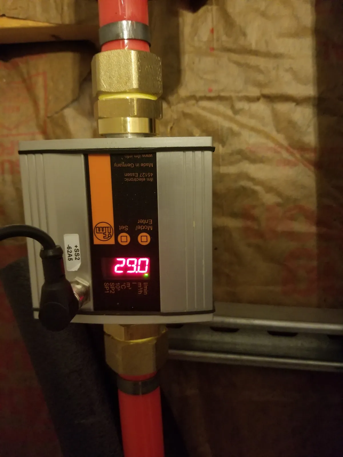
The first issue I had was related to a bad flow meter. This occurred on the first "chilly" morning, where there was a lot of fog (i.e., high humidity). I called Hotspot Energy, and I was sent another flow meter which was modified with silicone potting. Apparently, there is a condensation issue with the circuitry, so this should help. The factory supplied flow-meters are available via a multitude of places for a cheap price. They can be modified with the silicone potting easily (pop off the top, slather in some RTV, done). I was told that the v2 Chiltrix CX34 units have a different unit, but there was no "drop-in" replacement for the v1.
This all worked fine until about spring time, when I had what I thought was another flow meter failure. Read on to see what was really going on...
I'm now running on a completely different flow-meter set-up. The factory flow-meter has a three wire connection; black is 0v, red is +5v, and the yellow is a pulsed 50% duty +5v/0v. The pulses are at every 180° of the rotor's rotation (i.e. 50% duty cycle square wave). I found a great deal on an IFM SU8000 ultrasonic flow meter. This flow meter has G1 male threads on both ends. I obtained some G1 to 1" NPT adapters, and then some 1" NPT to 1" PEX barb adapters to plumb it in to my inside loop plumbing. Being that this is a 24v unit, I also obtained a 24 volt power supply. It's a generic 120VAC to 24VDC supply capable of an amp or so. After wiring up the flow meter and examining the digital output, it was evident that getting a 50% duty square wave at +5v was not going to be trivial- until I found a unit from Red Lion that handled this perfectly. I purchased a Red Lion AFCM0001 signal converter and Red Lion PGMMOD00 programming display. (AutomationDirect.com has a "white label" version of this for a bit cheaper; it's one of the units here) The AFCM0001 can convert almost any pulsed input, 1-10v, or 4-20ma process signal into almost any pulsed output, 1-10v, or 4-20ma process signal. I set up the SU8000 to output a 4-20ma analog signal, and set up the range from 0-35l/m. On the AFCM0001, I set the same range, and set the output to 50% duty square wave, and set the output range from 0-35Hz. The factory flow meter seems to put out 1Q - or 1Hz per l/m. After wiring everything up and programming, I ran a new factory flow-meter and my contrivance in parallel (not connected to the pulse input yet) to validate rates, and they matched up better than I would have ever expected. I used the +5v generated by the AFCM0001 and connected that to yellow, and the 0v to black. Overkill? Sure, but I don't think I'll ever have a problem again. I might even add in the OE meter and the ultrasonic, and have a Click PLC validate inputs and select which is "good", in case of a failure (and, of course, notify me). I'm a nerd.
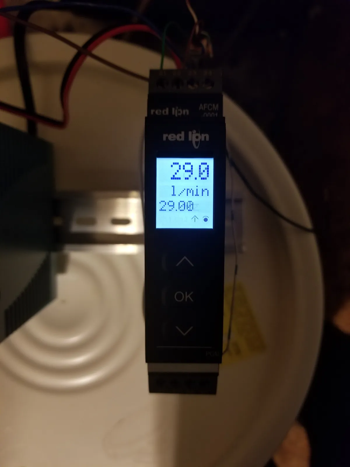
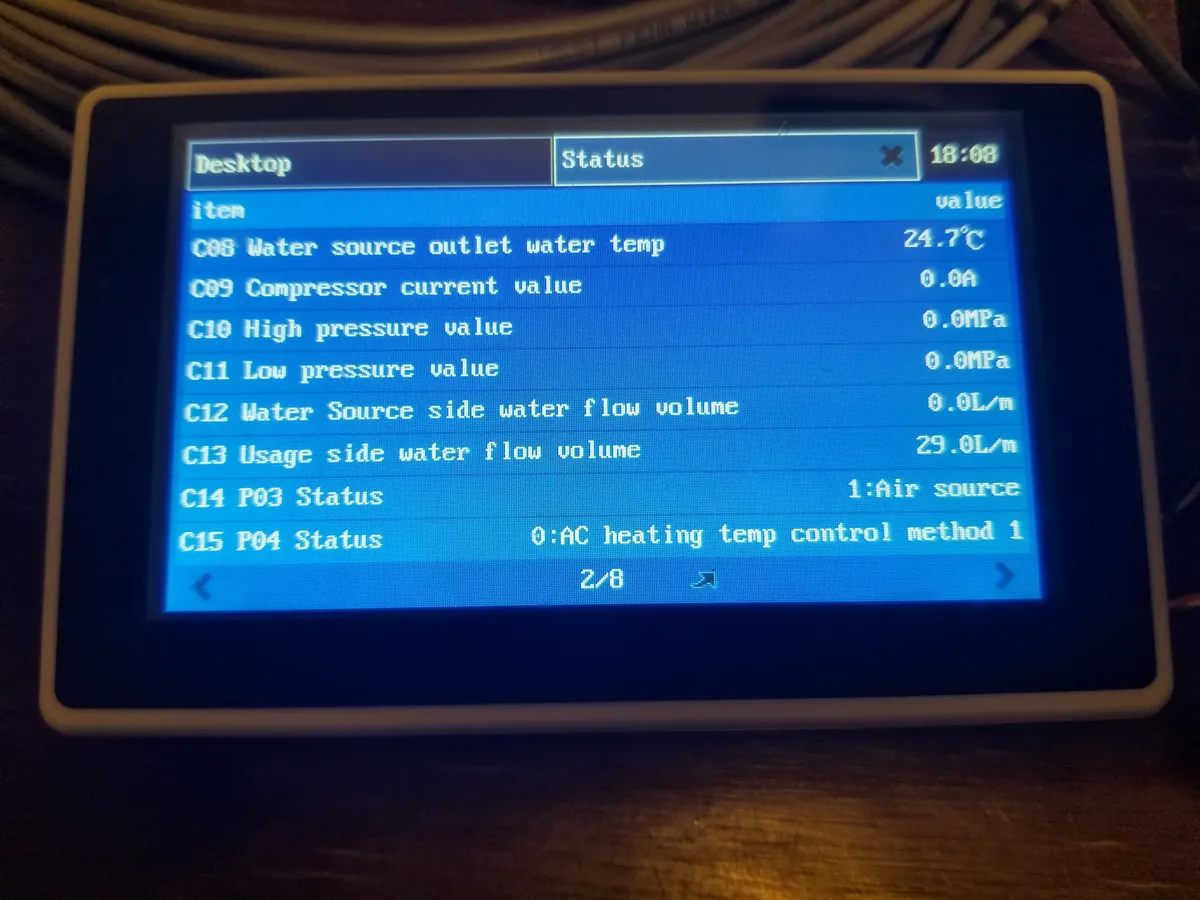 Chiltrix CX34 HMI showing agreement with the meter and converter output
Flow Meter UPDATE:
After installing the new flow meter, I noticed that the reported flow rate started high (26gal/min at speed "10") but would taper off despite the commanded speed remaining the same. Eventually this would taper down enough to cause a flow alarm. Listening to the pumps, I could hear them slowing down, so I started investigating the control signal. According to the pump (Wilo Yonos Para RS 25/7.5) manufacturer's data sheet, a 1kHz nominal frequency with PWM at 0-100% (<5% pump runs at maximum speed, 93-100% pump stops) controls the pump. I put a scope on the lines (with a differential probe) and lo and behold the noise was significant. When the compressor was running, especially at higher frequencies, the interference was substantial. The problem was, I thought I would be slick and use some 14-2-2 NM cable and use the second pair for the signal to the pump. This was, in retrospect, a dumb idea. The interference was crazy, since the signal is next to the AC lines. I rerouted the pump wiring and changed the way I had the internal wiring run (I had not taken this into account before, so the wiring was not very good with regards to interference!). Now, the signal looks great and the pumps run at the commanded speed without any dips. Another solution might have been to install a (4.7k??) resistor at the end of the line to help attenuate the noise.
Flow Meter UPDATE 2:
Well, things were great for a couple of weeks, until today- there was a flow alarm. It's been solid up until now. It's also the hottest day so far. I suspect the compressor drive frequency was higher than it has been, and some noise was induced in the pump control lines. I went ahead and added the 4.7k resistor, so we'll see how that pans out.
Flow Meter UPDATE 3:
The 4.7k resistor didn't help at all. The noise was almost nonexistent on the PWM lines without it anyway. Turns out I was missing a completely obvious issue; the system setting for minimum allowable flow rate (parameter P65 - "AC minimum water flow rate (Sets P5)") was set too high. I found out that my flow rate would occasionally drop to below 8l/m (the default) when the loop overshot a bit on cooling (i.e. loop temp of 8°C when set to 10°C) due to the glycol viscosity. I set parameter P65 to 4l/m which should still be more than enough flow. I also set P67 - "The lowest water flow of water source" to 4l/m as well. Problem solved; I have not had any issues for the past two months. Wonderful. Knowing the actual issue, I could go back to the factory flow meter (still installed in the outdoor unit, but currently disconnected), but at this point the ultrasonic meter is working perfectly and is much more nerd-tacular.
IPM Failures
Another issue I had happen a few times was the IPM board failing. The IPM board is basically the VFD driver for the compressor.
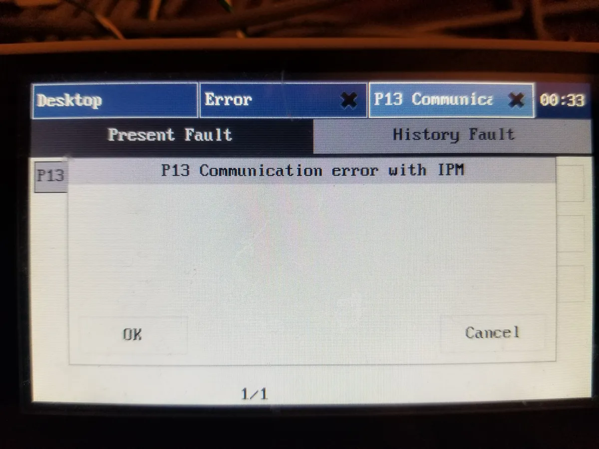
The first board failed, and I was sent a replacement. I was also told to install three MOVs at the input terminals to the system - 300v MOVs between L1-N, L2-N, and L1-L2. Everything was fine for a few months, then I had a weird issue where the system thought it was running the compressor, but nothing was happening. A reboot "fixed" it for a bit, but it kept happening. They sent me out a new IPM. After replacement, and installing the MOVs again, the IPM failed. They then sent a completely new design IPM this time, and it was installed with the MOVs (although the new one has protection, apparently). I also installed a Leviton 51240 240v 20 amp surge protector I got for a smokin' deal. It has 700v MOVs, so- nothing to write home about, but- the board protection, 300v MOVs at the input, the Leviton surge protector, and the Square-D surgebreaker in my panel should pretty much squelch anything short of a direct lightning strike, and trip the 20a breaker.
Since then, I have not had any further IPM issues.
Results?
I'm mostly quite happy with the system as it stands. I'll update more here as I think of it. In a future update to this, I will include pictures, as well as cleaning up the word salads herein. I'll also include the three versions of the manual I have, as well as the parameters the manuals show, as well as changes I've made and reasons for those changes.
Below are some documents including a parameter list I've put together that shows the parameters as well as what the defaults are (based on different versions of the manual) as well as my system's setting for each.
References
Chiltrix CX34 Version 1 Manual v1.5
Chiltrix CX34 Version 1 Manual v1.6